 Vivien
Self-healing of metallized film capacitors
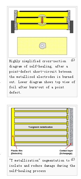
Metallized film capacitors have "self-healing" properties, which are not available from film/foil configurations.[11] When sufficient voltage is applied, a point-defect short-circuit between the metallized electrodes vaporizes due to high arc temperature, since both the dielectric plastic material at the breakdown point and the metallized electrodes around the breakdown point are very thin (about 0.02 to 0.05 µm). The point-defect cause of the short-circuit is burned out, and the resulting vapor pressure blows the arc away, too. This process can complete in less than 10 μs, often without interrupting the useful operation of the afflicted capacitor.[12]
This property of self-healing allows the use of a single-layer winding of metallized films without any additional protection against defects, and thereby leads to a reduction in the amount of the physical space required to achieve a given performance specification. In other words, the so-called "volumetric efficiency" of the capacitor is increased.
The self-healing capability of metallized films is used multiple times during the manufacturing process of metallized film capacitors. Typically, after slitting the metallized film to the desired width, any resulting defects can be burned out (healed) by applying a suitable voltage before winding. The same method is also used after the metallization of the contact surfaces ("schoopage") to remove any defects in the capacitor caused by the secondary metallization process.
The "pinholes" in the metallization caused by the self-healing arcs reduce the capacitance of the capacitor very slightly. However, the magnitude of this reduction is quite low; even with several thousand defects to be burned out, this reduction usually is much smaller than 1% of the total capacitance of the capacitor.[13]
For larger film capacitors with very high standards for stability and long lifetime, such as snubber capacitors, the metallization can be made with a special fault isolation pattern. In the picture on the right hand side, such a metallization formed into a “T” pattern is shown. Each of these “T” patterns produces a deliberately narrowed cross-section in the conductive metallization. These restrictions work like microscopic fuses so that if a point-defect short-circuit between the electrodes occurs, the high current of the short only burns out the fuses around the fault. The affected sections are thus disconnected and isolated in a controlled manner, without any explosions surrounding a larger short-circuit arc. Therefore, the area affected is limited and the fault is gently controlled, significantly reducing internal damage to the capacitor, which can thus remain in service with only an infinitesimal reduction in capacitance.[14]
In field installations of electrical power distribution equipment, capacitor bank fault tolerance is often improved by connecting multiple capacitors in parallel, each protected with an internal or external fuse. Should an individual capacitor develop an internal short, the resulting fault current (augmented by capacitive discharge from neighboring capacitors) blows the fuse, thus isolating the failed capacitor from the remaining devices. This technique is analogous to the "T metallization" technique described above, but operating at a larger physical scale. More-complex series and parallel arrangements of capacitor banks are also used to allow continuity of service despite individual capacitor failures at this larger scale.