
 Vivien
Film Capacitor construction and features
Film capacitors are made out of two pieces of plastic film covered with metallic electrodes, wound into a cylindrical shaped winding, with terminals attached, and then encapsulated. In general, film capacitors are not polarized, so the two terminals are interchangeable. There are two different types of plastic film capacitors, made with two different electrode configurations:
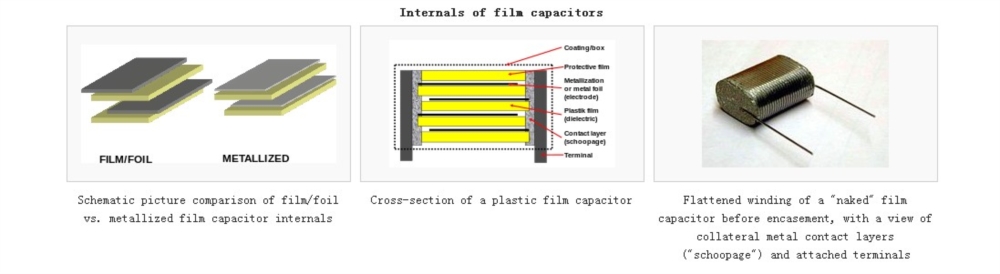
- Film/foil capacitors or metal foil capacitors are made with two plastic films as the dielectric. Each is layered with a thin metal foil, usually aluminum, as the electrodes. Advantages of this construction type are easy electrical connection to the metal foil electrodes, and its ability to handle high current surges.
- Metallized film capacitors are made of two metallized films with plastic film as the dielectric. A very thin (~ 0.03 µm[2]) vacuum-deposited aluminum metallization is applied to one or both sides to serve as electrodes. This configuration can have "self-healing" properties, in that dielectric breakdowns or short circuits between the electrodes do not necessarily lead to the destruction of the component. With this basic design, it is possible to make high quality products such as "zero defect" capacitors and to produce wound capacitors with larger capacitancevalues (up to 100 µF and larger) in smaller cases (high volumetric efficiency) compared to film/foil construction. However, a disadvantage of metallized construction is its limited current surge rating.
A key advantage of modern film capacitor internal construction is direct contact to the electrodes on both ends of the winding. This contact keeps all current paths to the entire electrode very short. The setup behaves like a large number of individual capacitors connected in parallel, thus reducing the internal ohmic losses (ESR) and the parasitic inductance (ESL). The inherent geometry of film capacitor structure results in very low ohmic losses and a very low parasitic inductance, which makes them especially suitable for applications with very high surge currents (snubbers) and for AC power applications, or for applications at higher frequencies.
Another feature of film capacitors is the possibility of choosing different film materials for the dielectric layer to select for desirable electrical characteristics, such as stability, wide temperature range, or ability to withstand very high voltages. Polypropylene film capacitors are specified because of their low electrical losses and their nearly linear behavior over a very wide frequency range, for stability Class 1 applications in resonant circuits, comparable only with ceramic capacitors. For simple high frequency filter circuits, polyester capacitors offer low-cost solutions with excellent long-term stability, allowing replacement of more expensive tantalum electrolytic capacitors. The film/foil variants of plastic film capacitors are especially capable of handling high and very high current surges.
Typical capacitance values of smaller film capacitors used in electronics start around 100 picofarads and extend upwards to microfarads.
Unique mechanical properties of plastic and paper films in some special configurations allow them to be used in capacitors of very large dimensions. The larger film capacitors are used as power capacitors in electrical power installations and plants, capable of withstanding very high power or very high applied voltages. The dielectric strength of these capacitors can reach into the four-digit voltage range.
Internal structure[edit]
The formula for capacitance (C) of a plate capacitor is:

(ε stands for dielectric permittivity; A for electrode surface area; and d for the distance between the electrodes).
According to the equation, a thinner dielectric or a larger electrode area both will increase the capacitance value, as will a dielectric material of higher permittivity.[3]
Example manufacturing process[edit]
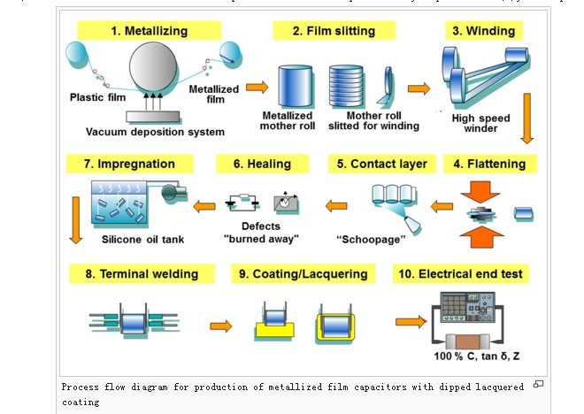
The following example describes a typical manufacturing process flow for wound metallized plastic film capacitors.
- Film stretching and metallization — To increase the capacitance value of the capacitor, the plastic film is drawn using a special extrusion process of bi-axial stretching in longitudinal and transverse directions, as thin as is technically possible and as allowed by the desired breakdown voltage.[4][5][6] The thickness of these films can be as little as 0.6 µm. In a suitable evaporation system and under high vacuum conditions (about 1015 to 1019 molecules of air per cubic meter) the plastic film is metallized with aluminum or zinc. It is then wound onto a so-called "mother roll" with a width of about 1 meter.
- Film slitting — Next, the mother rolls are slit into small strips of plastic film in the required width according to the size of the capacitors being manufactured.
- Winding — Two films are rolled together into a cylindrical winding. The two metallized films that make up a capacitor are wound slightly offset from each other, so that by the arrangement of the electrodes one edge of the metallization on each end of the winding extends out laterally.
- Flattening — The winding is usually flattened into an oval shape by applying mechanical pressure. Because the cost of a printed circuit board is calculated per square millimeter, a smaller capacitor footprint reduces the overall cost of the circuit.
- Application of metallic contact layer ("schoopage") — The projecting end electrodes are covered with a liquefied contact metal such as (tin, zinc or aluminum), which is sprayed with compressed air on both lateral ends of the winding. This metallizing process is named schoopage after Swiss engineer Max Schoop, who invented a combustion spray application for tin and lead.[7]
- Healing — The windings which are now electrically connected by the schoopage have to be "healed". This is done by applying a precisely calibrated voltage across the electrodes of the winding so that any existing defects will be "burned away" (see also "self-healing" below).
- Impregnation — For increased protection of the capacitor against environmental influences, especially moisture, the winding is impregnated with an insulating fluid, such as silicone oil.
- Attachment of terminals — The terminals of the capacitor are soldered or welded on the end metal contact layers of the schoopage.
- Coating — After attaching the terminals, the capacitor body is potted into an external casing, or is dipped into a protective coating. For lowest production costs some film capacitors can be used "naked", without further coating of the winding.
- Electrical final test — All capacitors (100%) should be tested for the most important electrical parameters, capacitance (C), dissipation factor (tan δ) and impedance (Z).
The production of wound film/metal foil capacitors with metal foil instead of metallized films is done in a very similar way.
As an alternative to the traditional wound construction of film capacitors, they can also be manufactured in a “stacked” configuration. For this version, the two metallized films representing the electrodes are wound on a much larger core with a diameter of more than 1 m. So-called multi-layer capacitors (MLP, Multilayer Polymer Capacitors) can be produced by sawing this large winding into many smaller single segments.[8][9] The sawing causes defects on the collateral sides of the capacitors which are later burned out (self-healing) during the manufacturing process. Low-cost metallized plastic film capacitors for general purpose applications are produced in this manner.[10] This technique is also used to produce capacitor "dice" for Surface Mount Device(SMD) packaged components.

